
Technical Note – JOCR Oct – Dec 2011
Dr. Mangal Parihar,
Center for Limb Lengthening & Reconstruction,
Mangal Anand Hospital,Swastik Park, Chembur, Mumbai -71
E-mail : mangalparihar@gmail.com
Abstract: Full-length hip-to-ankle radiographs are an important part of planning and execution of any realignment procedure of the lower limb. This technical note describes a simple and inexpensive technique to obtain plain, standing, full-length hip-to-ankle radiograph using regular x-ray plates.
Keywords: alignment; hip-to-ankle radiograph; corrective osteotomy
Proper imaging with radiographs plays an important role in preoperative planning and also assessing postoperative radiographic results. One of the major aims of any kind of lower limb corrective surgery such as corrective osteotomy or total knee arthroplasty, is restoration of the mechanical axis of the limb [1]. To achieve this, one needs to be able to assess the existing axis, plan the degree of correction to achieve the desired limb alignment and also to verify whether the post operative alignment obtained was as planned and desired. All these require obtaining proper standing, full-length hip-to-ankle radiographs [2]. However, most centres, especially in developing countries, lack the facilities for obtaining such fulllength radiographs. Typically these full-length radiographs are obtained using a long cassette with an X-ray film of the appropriate length. The X-ray cassette has to be specially made to order, and is expensive because of the three screens that are needed inside. In addition, when a single long cassette is used, one has to use a graduated wedge in front of the x-ray tube, for attenuating the x-ray beam in the lower portion of the cassette to avoid overexposure. We describe here a simple and costeffective technique of obtaining full-length radiographs of the lower limb in a single exposure using 3 standard x-ray cassettes.
We use a simple wooden stand, which can be made by any carpenter, to hold the x-ray cassettes (Fig. 1A). Since the commonly available cassettes are 10 x 12 inches, 12 x 12 inches and 12 x 15 inches in dimension, the transverse length of the stand should be 12 inches. A larger transverse size could be used, provided, three cassettes of the same size are available.
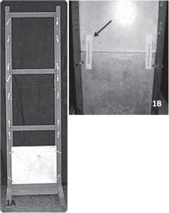
Three regular x-ray cassettes are stacked on each other, length-wise, taking care that none of the joints comes in the area between the cassettes. Two linear markers of a fixed length are placed on either side of the cassette, such that they overly both the upper and the lower cassette equally. We use 8 inch long Kirschner wires for this purpose (Fig. 1B). The patient stands on a low stool so that the plantar surface of the foot is above the edge of the lowermost cassette (Fig. 2). A magnification marker if available is applied in the plane of the bone, and perpendicular
to the x-ray beam.
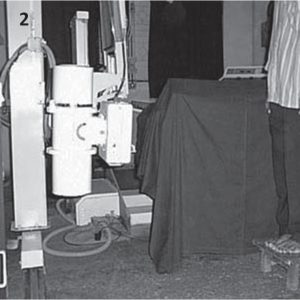
The x-ray tube is placed 6 feet away, and at the level of the knees (Fig. 2). The exposure factors (KV & maS) used is same as those used for a hip radiograph. This will lead to some overexposure of the lower two cassettes, which can be compensated for by under-developing the x-ray films. In places where automatic processing is used, a triangular aluminium wedge will need to be used to attenuate the beams going to the lower two cassettes. When the films are dried, the three x-rays are kept on a light box of adequate dimensions. Between each of
the three films, one needs to put in a 3 cm strip of (spoilt) film. This simulates the distance between the films when they are in the cassettes (Fig. 3A). The distance between the two intensifying screens is then 3 cms. The correct distance between films can be further judged by using markers of known, equal lengths at all four sites.

Since the markers are practically on the plane, the magnification of the markers is negligible.
Vertical alignment is ensured by keeping the shadows of the markers previously mentioned, in a straight line (Fig. 3B). Since one marker is used on either side, the chances of the films being angled in relation to each other are further decreased. Use of a magnification marker, if available further increases the accuracy of lengths measured from this x-ray. In this position the three films are then joined using transparent tape to create a single, composite, full length x-ray. Relative measurements of limb length discrepancy and angular measurements can now be obtained accurately and reliably. With the use of a magnification marker, even absolute measurements of length can be made very precisely.
A full-length hip-to-ankle radiograph is an important part of planning and execution of a lower limb realignment procedure. Obtaining such radiographs may be challenging as the facilities for the same are expensive and not widely available. A simple and inexpensive technique to obtain plain, standing, fulllength hip-to-ankle radiograph is described here. This technique uses regular plain x-ray cassettes to obtain full-length radiographs on which both angular
and linear measurements can be made with a fair degree of accuracy and with minimal magnification errors. Although the tools for this radiographic technique are easy to obtain and set-up, a fairly experienced x-ray technician well versed in this technique may be required to use it regularly in practice. Like most new techniques, this may involve some initial training and learning curve before it can be adopted in routine practice. The authors had developed this technique and were using it successfully over the last 10 years as part of routine pre- and postoperative radiographic assessment of patients undergoing Ilizarov procedures. The author has found these radiographs to be accurate for both preoperative planning and postoperative assessment.
References
- 1.Paley D, Herzenberg JE, Tetsworth K, McKie J, Bhave A. Deformity planning for frontal and sagittal plane corrective osteotomies. Orthop Clin North Am. 1994; 25:425-465. [Google Scholar | PubMed]
- 2.Paley D. Frontal plane mechanical and anatomic axis planning. In: Paley D, ed. Principles of Deformity Correction. New York, NY: Springer-Verlag; 2002:61-97. [Google Scholar | PubMed]
Related Articles in Journal of Orthopaedic Case Reports
 April 10, 2024 Evaluating the Efficacy and Safety of Combined Administration of Systemic and Topical Tranexamic Acid in Total Knee Arthroplasty
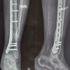 November 1, 2025 Clinical and Functional Outcome of Distal Tibial Fractures Treated with Minimally Invasive Percutaneous Plate Osteosynthesis Technique using Anatomical Distal Tibial Plate: A Case Series
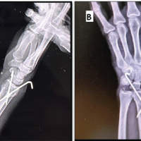 November 1, 2024 Hematoma Block as an Alternate Mode of Anesthesia for Management of Extra-Articular Distal End Radius Fracture with Percutaneous K-Wire Fixation in Emergency Department
 July 10, 2019 Unusual Presentation of Koch’s Spine Involving Posterior Elements of Vertebra– A Case Report